• Published on

    Miscellaneous Ball Handling Components

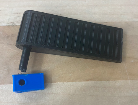
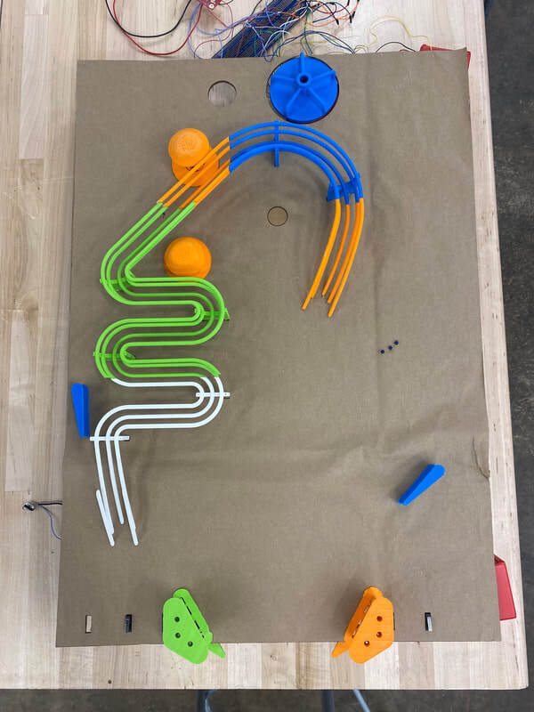
    I experimented with making the plunger to shoot the ball at the beginning. This was done by threading a steel and attaching a comfortable rubber stopper.

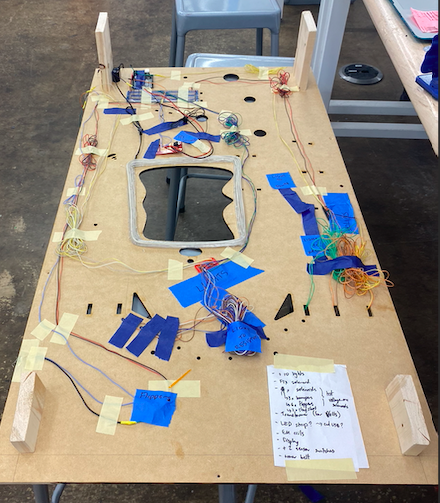
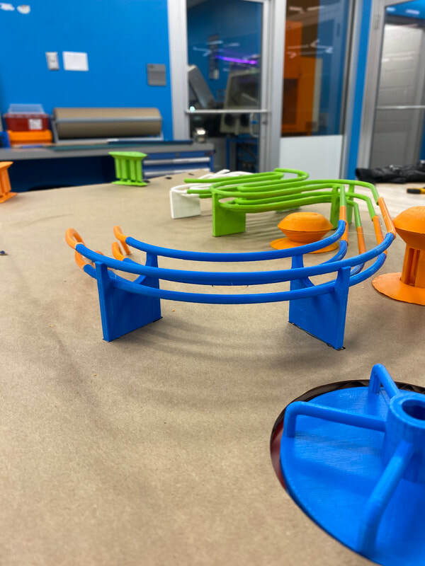
    I also worked on integrating the solenoids into my bumpers, slingshots and flipper. I experimented with various solenoids and even made a higher fidelity version with copper wire.

    To activate the bumper the arduino must detect contact between the ball and the bumper. To do this I created an open circuit with an exposed side on the ramp of the bumper and one on the face of the pinball machine. This means when the ball rolls over the ramp it will complete the circuit, activate the bumper and get shot away. I experimented with thin copper sheets, copper tape and AlFoil. AlFoil was the best because it was easily moldable, cheap and did not short circuit with itself like the copper tape did.

    The various progressions of my design of solenoids and solenoid activated components is at this link. 
    Image description
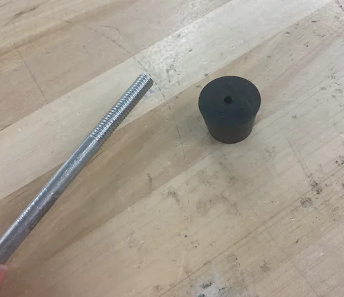
    Threaded rod with grip
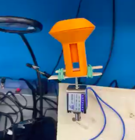
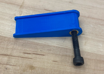
    Bumper solenoid mockup
  • Published on

    Flipper Redesign

    After a couple worries about breakages on the axle of the flipper, I redesigned it to use off-the-shelf components. I used a threaded insert for plastic and a bolt as the axle. This bolt fit very easily and smoothly through my bearing. Another advantage of using the bolt is that I can adjust the flippers' height off the board by screwing the bolt in more or less.  

    Additionally, for storage it is much simpler to remove the bolt and take the flipper off to avoid damage.

    In future I want to use imperial bolts with a hex head. This means the attachment to the rest of the flipper mechanism can just be the negative to the hex head and the connection between those two parts can be simplified. 
    First flipper design with weak axle
    Flipper design with bolt axle
  • Published on

    End of Semester Summary

    Throughout the semester I spent time taking the code I had previously created and forming an electrical harness for easy debugging on the back. A big problem that occurred was my joints breaking at the protoboard connection. To compensate I added stress relief to the joints.

    Additionally, I spent time manufacturing the machine into a higher fidelity prototype. This involved lasercutting the base (mdf with an acrylic cover), adding legs and creating components which effectively fit in the holes. 

    The component designs were increased to have more high fidelity models which also accounted for the connections each component would need to have to the board. 
    Electrical harness
  • Published on

    End of Semester Summary

    This semester I have created a prototype of a pinball machine with the components 3D printed and working electronics for the main components. 

    In the future I would like to manufacture the components out of appropriate heavy duty materials: acrylic and plywood for the base; delrin and rubber for the slingshots and bumpers and flippers; aluminium tubing for the habitrail. I would also like to improve my code with switch statements and shift registers. Finally, to manufacture the individual parts, I need to make the CAD reflect the tools I will use to manufacture each part. For example, I will use a 3 axis CNC for the flippers but my current design has overhangs. Therefore it must be divided into three components with mates. 

    Front View

    Top View

    Back View

  • Published on

    Integration of Code Parts

    I have combined all of my previous code into a single script. There are no delays included so any button presses will not be missed due to the code waiting at the delay. The lights are activated once the points reach a certain threshold and the flipper drops from 50V to 5V to avoid the coil burning out (these are both described in more detail in previous blog posts).

    In future, I would like to change my code to switch statements so the if/else statements that have already been confirmed do not need to be asked each loop. Additionally, since the Arduino uno does not have enough pins for the full pinball machine I would like to eventually use shift registers to control the different pins.

    Working Code with Lights, Point Calculation, and Flipper Actuation 

    To see code please press Read More --->
  • Published on

    Initial Electronics

    I created the initial code for the most important electrical components. 

    This code was made as a proof of concept and includes delays, which will not be used once all of the code segments are integrated. 

    The aim of the flipper code is to do the aforementioned switch between 50V and 5V with PWM. All the bumpers and slingshots will be controlled with almost identical code. The lights flash in order once the points are greater than a certain value (not included in this code). Every time the ball rolls over a switch, a certain number of points are added to the point tally. Finally the display writes these points on an LCD display. 

    In future I will combine all this code into one block that runs through each loop.  

    Electrical Schematics

    Various circuits

    Arduino Electrical Schematic

    Arduino circuits

    Code

    Attached is the functional code for the flippers, the lights, the point calculators, and the display.